175 Results
View results:
Sort by:
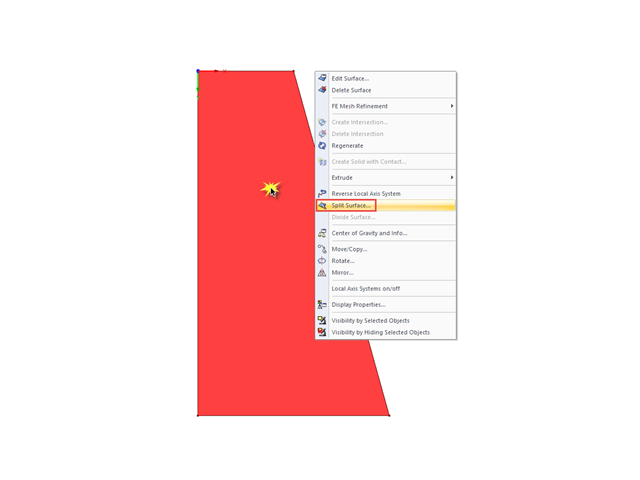
If you want to split a surface limited by four sides into several surfaces, the easiest way to do this is to use the "Split Surface" function.
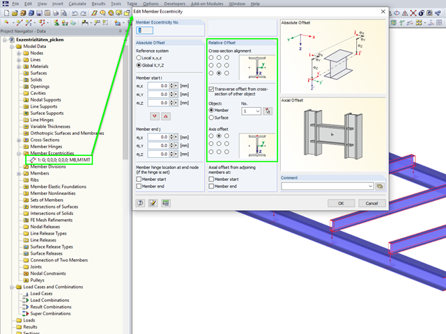
In RFEM 5 and RSTAB 8, you can enter eccentricities for surfaces and members using the convenient "Select" function.
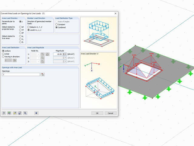
With the "Convert Area Loads on Openings to Line Loads" function, you can automatically take into account, for example, wind loads applied on windows or other loads applied on non‑bearing structures not represented in the model in openings. You can access this function via "Tools" → "Generate Loads" → "From Area Loads on Openings...."
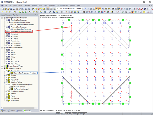
In RF‑CONCRETE Surfaces, the design of the surface reinforcement is done by means of a freely definable reinforcement mesh. In RF‑CONCRETE Surfaces, you can display the reinforcement direction by activating the reinforcement arrow that represents it.
From time to time, it may happen that the axis systems of some surfaces in the model do not correspond to each other.
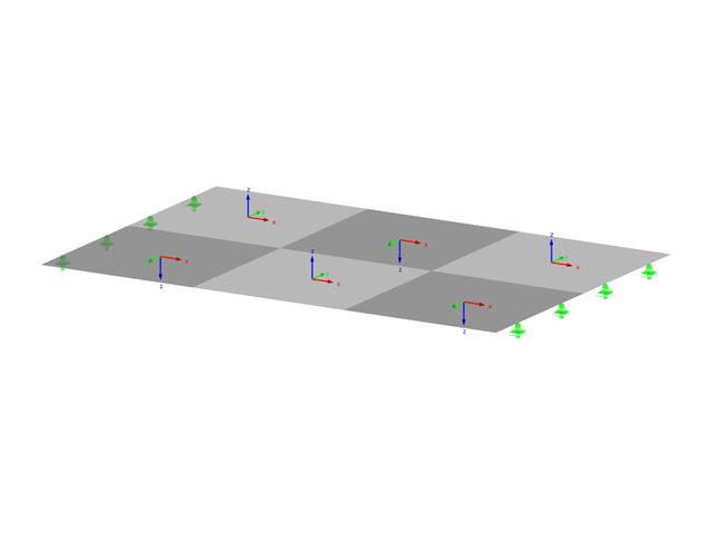
In RFEM, there are various options for defining point and surface supports.

RF‑CONCRETE Surfaces for RFEM 5 allows you to use averaged internal forces for design of concrete surfaces.
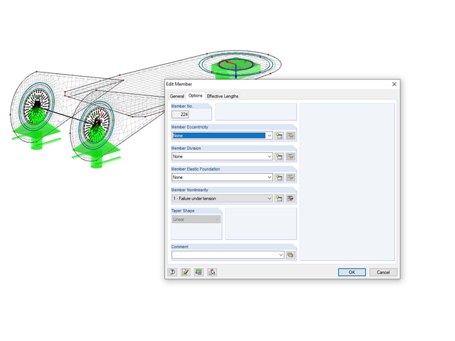
The simplest way to model a bolt connection in RFEM 5 is to define a node in the center of a hole, then connect it by means of internal members to the surface.
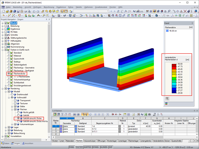
RFEM 5 allows you to show the variable surface thicknesses as a color gradient.
The elastic‑plastic material model in RFEM 5 allows you to calculate surfaces and solids with plastic material properties and to carry out a stress evaluation. This material model is based on the classic von Mises plasticity.

Shrinkage and creep are time-dependent deformation properties of concrete that usually have to be considered in the serviceability limit state design.
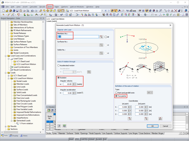
With RFEM, you can generate member, surface, or solid loads resulting from motions. Thus, for example, braking or acceleration forces can be generated automatically from linear movements or from rotational movements on a structural system.
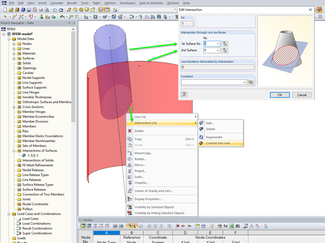
If you want to model two intersecting surfaces, RFEM offers you the possibility to create the section line automatically. In the program, this function is referred to as intersection. When generating an intersection, the modeled surface is split into components. This has the advantage that the components can be taken into account in the determination of the internal forces, or deactivated.
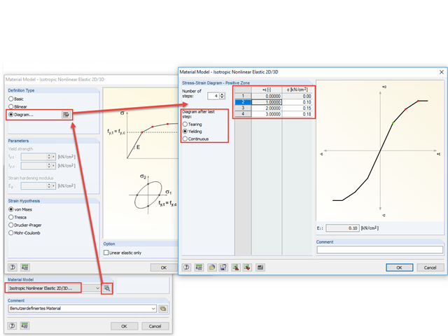
With the nonlinear elastic material model in RFEM 5, you can calculate and carry out a stress analysis of surfaces and solids with nonlinear material properties.

For cross‑laminated structures with large spans, downstand beams or hybrid structures are often used. They can be modeled in RFEM 5 by using surfaces and member cross‑sections. In both structural systems, curved downstand beams are also possible without any problems. In the case of the curved surface, the member is always appropriately generated by means of the automatic member eccentricity with the thickness distance of the surface and the member. The downstand beam can also be connected flexibly by means of a line release.
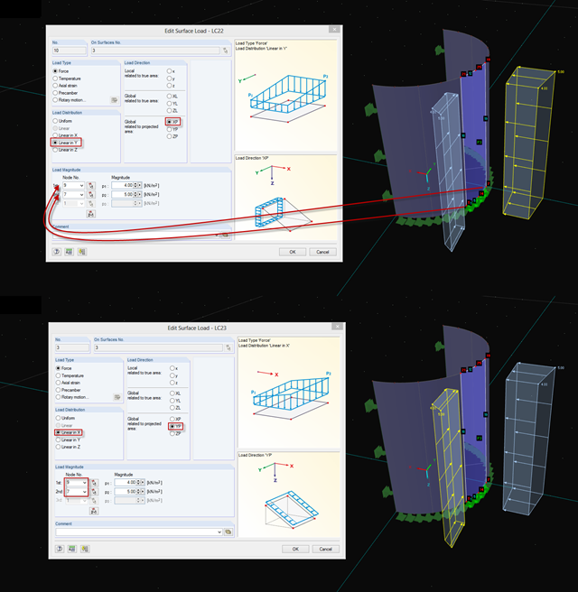
In RFEM 5 and RSTAB 8, you can generate surface loads like wind and snow by means of the implemented load generator. On frameworks, these surface loads are also displayed as surface loads in the graphic by default.
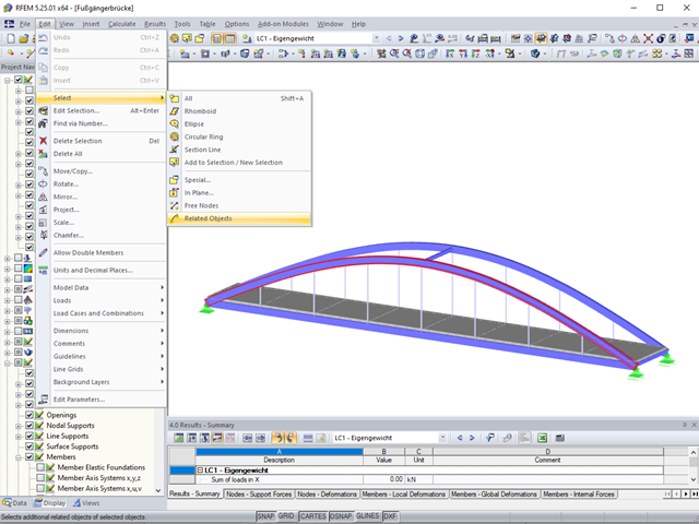
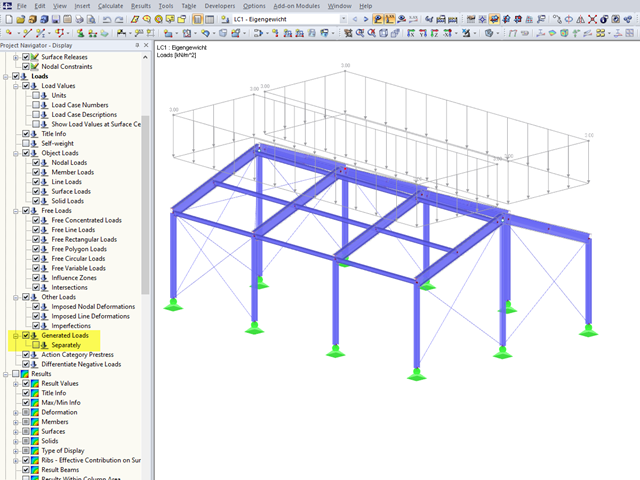
Sometimes it is necessary to add related objects, such as nodes and lines of a surface, to the selection in order to edit parts of the model.
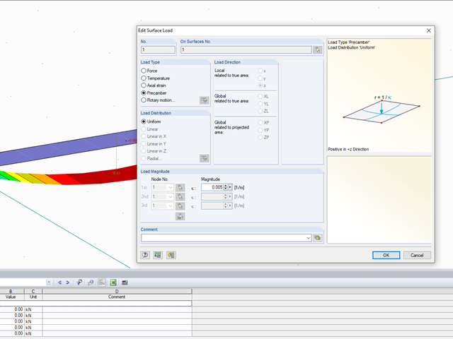
In RFEM, you have the option to consider an imperfection on surfaces. You can do this by means of the "Precamber" surface load.

If the geometry of a surface for which you must remove some of the existing boundary lines changes subsequently, you do not need to redefine the surface.
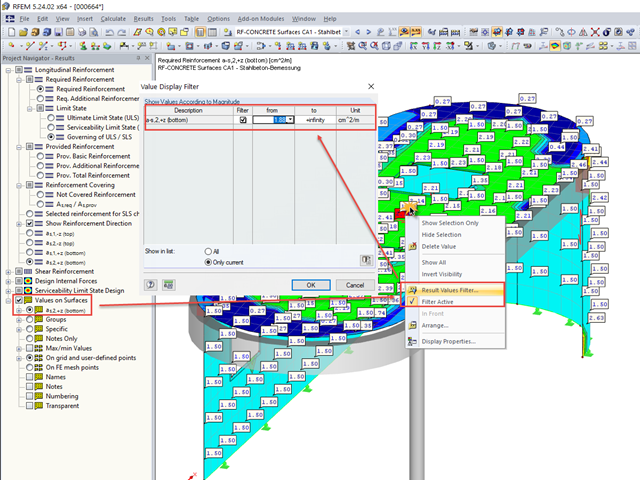
In many cases, it is necessary to filter the results for the display of values on surfaces so as not to show all the numbers. In displaying the reinforcement arrangement, you can, for example, hide values that are below the already used basic reinforcement.
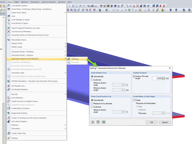
RFEM allows you to automatically generate surfaces from modeled members. This has the advantage that, for example, the surface thicknesses of a steel section are generated automatically.

For relatively large or relatively small surfaces, it can happen that the automatically created result values do not fit the model: In the case of large surfaces, there can be too many result values; in the case of small surfaces, too few.
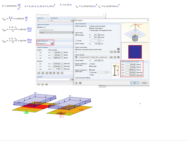
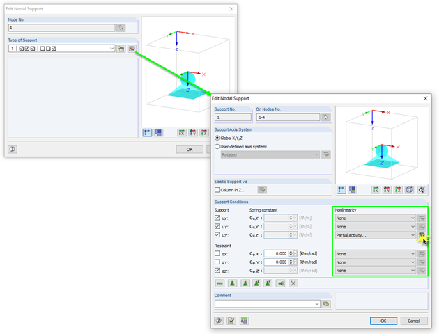
Often, it happens that stress peaks occur on a nodal support that is attached to a surface. You can avoid such singularities by modeling the nodal support as a column.
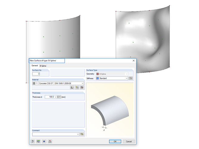
Instead of a quadrangular surface, you can use a B‑spline surface. The shape of this can be adjusted retrospectively, using the integrated help nodes. Depending on the necessary surface complexity, you can create a B‑spline surface with 3 × 3 or 4 × 4 help nodes.

In RFEM 5 and RSTAB 8, you can save problems and warnings occurring during the model check as an extra view. This way, you can easily work through the hints and messages, one after the other, cleaning the model. The function is available for double nodes, overlapping members/lines, and surfaces.

You can use the elastic support option to avoid singularities due to a fixed nodal support in RFEM. This can be defined directly in the dialog box of the nodal support as a column in Z. It is necessary to take into account the geometry of the column, the material, and the support conditions. Here, we want to look at the option of modeling the column as a surface foundation.

The new "Result Beam" member type in RFEM 5 allows you to determine the load sums of individual floors easily. To do this, model a member in the relevant floor or in all floors, then specify the relevant walls as inclusive objects in the parameters of the result beam. RFEM then integrates the surface internal forces into member internal forces.
If you want to apply, for example, wind loads to a circular cylinder as defined in EN 1991‑4, Clause 7.9, proceed as follows.
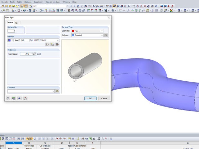
It may become necessary to analyze pipe cross‑sections as surface models in plant engineering in particular, but also when analyzing details of structural systems. For this purpose, RFEM offers the option to create pipe cross‑sections automatically by means of a line.
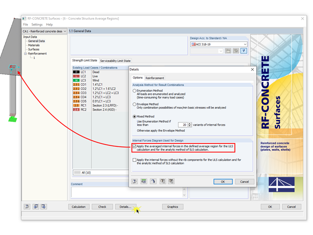
The averaged internal forces from the previously defined average regions can also be used for designing concrete surfaces. To do this, click [Details] in RF‑CONCRETE Surfaces, then select the corresponding check box. This function is accessible only if you previously defined an average region.